EVPN/VXLAN Deep Dive
A practical, engineering-focused guide to spine-leaf fabrics, routed underlays, MP-BGP EVPN control plane, VXLAN data plane, L2/L3 VNIs, VRFs, RD/RT policy, route types, packet walks, Cisco NX-OS verification and troubleshooting.
1. The mental model: separate “how we learn” from “how we forward”
The single most important idea in EVPN/VXLAN is that the control plane and data plane are different systems with different jobs.
| Plane | Technology | Job | Transport |
|---|---|---|---|
| Control plane | EVPN carried by MP-BGP | Distribute endpoint and prefix reachability, policy and tenancy information | BGP over TCP 179 |
| Data plane | VXLAN | Encapsulate actual Ethernet/IP traffic between VTEPs across the routed fabric | UDP 4789, outer IP between VTEPs |
Therefore, when you inspect an EVPN Type-2 or Type-5 route, an RD, an RT, or an EVPN import policy, no user packet is being VXLAN-encapsulated at that moment. Those are control-plane objects. VXLAN appears when real traffic is forwarded.
2. Why data centres moved beyond traditional VLAN + STP
A small network can absolutely extend VLANs with trunks and use STP to prevent loops. The problem is not that traditional Ethernet “does not work”; the problem is what happens when the environment grows to hundreds or thousands of racks, tenants and workloads.
- Large Layer-2 failure domains: broad flooding and topology events affect more devices.
- STP blocks capacity: redundant physical links may be intentionally blocked to avoid loops instead of being used simultaneously.
- Operational coupling: adding a VLAN often means touching many intermediate devices and trunks.
- Scale limits: the 802.1Q VLAN identifier is 12 bits, with roughly 4094 usable VLAN IDs per local switching context.
- Multi-tenancy: different tenants may legitimately reuse the same local VLAN IDs and overlapping IP space.
- Predictability: modern data-centre fabrics prefer routed links, equal-cost multipath and repeatable topologies.
EVPN/VXLAN keeps the physical fabric routed and stable, while creating logical Layer-2 and Layer-3 tenant networks on top.
3. Spine–Leaf architecture
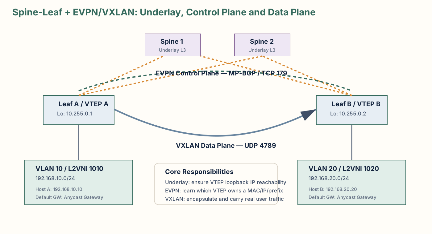
In a classic Clos-style spine-leaf design, every Leaf connects to every Spine, and Leafs normally do not require direct east-west links to other Leafs. Servers, firewalls and appliances attach to Leafs. Spines provide transit across the fabric.
Access/edge of the fabric. Hosts attach here. In VXLAN fabrics the Leaf usually acts as a VTEP.
High-speed L3 transit. It forwards based on the outer IP header. It does not need the tenant VLAN or inner MAC table to forward VXLAN traffic.
Multiple equal-cost paths can be active at the same time. This uses all uplinks and gives predictable scale.
A well-designed routed underlay has a simple objective: every VTEP loopback can reach every other VTEP loopback. Once that exists, the overlay can be built on top.
4. Underlay vs overlay
Underlay
The underlay is the real IP network between network devices. It may use eBGP, OSPF or IS-IS. In many modern fabrics eBGP is popular because it gives simple failure domains and explicit policy.
Leaf A loopback / VTEP: 10.255.0.1/32
Leaf B loopback / VTEP: 10.255.0.2/32

Goal of underlay:
10.255.0.1 must have IP reachability to 10.255.0.2
10.255.0.2 must have IP reachability to 10.255.0.1
Overlay
The overlay provides tenant connectivity independent of physical rack location. EVPN distributes control-plane information. VXLAN carries data-plane traffic between VTEPs.
5. VXLAN: the data-plane encapsulation
VXLAN (Virtual Extensible LAN) transports a logical Ethernet segment across an IP network. The ingress VTEP wraps the original frame in a VXLAN/UDP/IP envelope; the remote VTEP removes that envelope.
Important fields
| Field | Meaning |
|---|---|
| VNI | 24-bit VXLAN Network Identifier. It identifies a logical overlay segment/context. |
| UDP destination | 4789 for standard VXLAN data traffic. |
| Outer source IP | Ingress VTEP address. |
| Outer destination IP | Egress VTEP address. |
| Inner frame | The original tenant Ethernet frame / IP packet. |
The Spine normally cares only about the outer source/destination IP. That is why the physical core can remain tenant-agnostic.
Outer Ethernet
Outer IP: 10.255.0.1  -> 10.255.0.2
UDP: src ephemeral    -> dst 4789
VXLAN: VNI 1010
Inner Ethernet:
    Host-A MAC -> Host-C MAC
Inner IP:
    192.168.10.10 -> 192.168.10.20
6. EVPN: the control plane
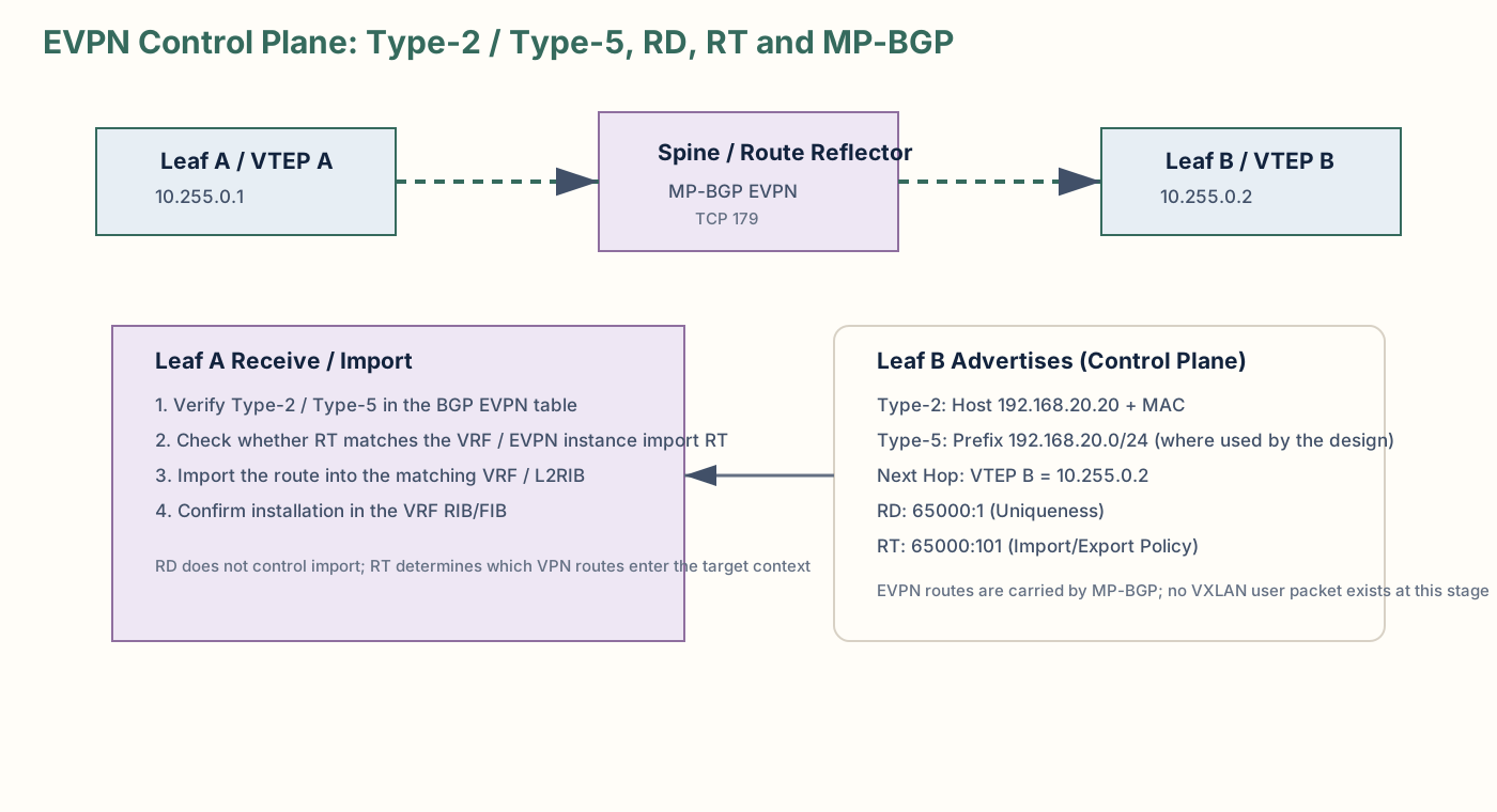
EVPN is a BGP address family that carries reachability information for Ethernet VPN services. In a VXLAN fabric, it replaces much of the “flood and learn everywhere” behaviour with a distributed control plane.
EVPN information is carried by MP-BGP (Multiprotocol BGP) over TCP 179. The EVPN routes can include MAC addresses, host IPs, IP prefixes, Ethernet segment information, next-hop VTEP information and policy attributes such as Route Targets.
7. VLAN, L2 VNI, VRF: the hierarchy
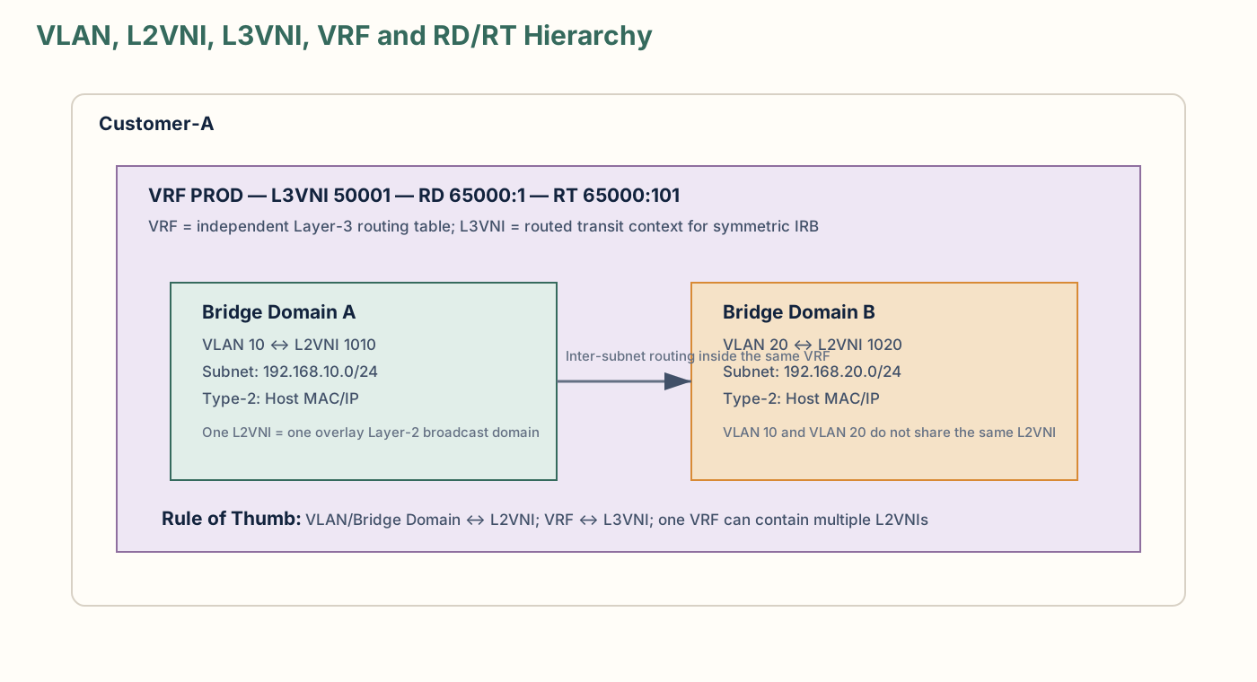
One source of confusion is trying to make VLAN, VNI and tenant mean the same thing. They are not the same object.
| Object | Typical scope | What it represents |
|---|---|---|
| VLAN | Local switching context | A local Layer-2 broadcast domain / bridge domain identifier. |
| L2 VNI | Overlay fabric | A VXLAN Layer-2 segment. Typically one L2 VNI maps to one bridge domain/VLAN on each participating Leaf. |
| VRF | Tenant / routing context | A separate Layer-3 routing table. |
| L3 VNI | Overlay fabric | The VXLAN identifier for an IP-VRF in symmetric IRB designs; commonly one L3 VNI per tenant VRF. |
Example
Tenant: Customer-A
VRF: PROD
  VLAN 10  -> L2 VNI 1010 -> 192.168.10.0/24
  VLAN 20  -> L2 VNI 1020 -> 192.168.20.0/24
  VLAN 30  -> L2 VNI 1030 -> 192.168.30.0/24

VRF PROD -> L3 VNI 50001
VLAN 10 and VLAN 20 do not normally share the same L2 VNI. They are different broadcast domains, so they map to different L2 VNIs. The fact that they belong to the same customer is expressed at the Layer-3 tenancy/VRF level, not by forcing them into one L2 VNI.
Why can VNI scale far beyond 4094?
The 4094 number is a local VLAN-ID constraint. A large multi-tenant fabric can reuse the same local VLAN ID on different Leafs or in different tenant contexts while mapping those local bridge domains into globally distinct VNIs. The VNI field is 24 bits, giving roughly 16.7 million possible identifiers before implementation-specific reservations.
Example:
Leaf 1:
  local VLAN 100 -> Tenant A L2 VNI 10100

Leaf 40:
  local VLAN 100 -> Tenant B L2 VNI 20200

The local VLAN ID is the same.
The overlay segment is different because the VNI is different.8. L3 VNI, distributed routing and IRB
An L3 VNI is associated with an IP-VRF and is used for routed tenant traffic in common symmetric IRB (Integrated Routing and Bridging) designs.
Suppose Customer-A has:
VRF PROD
  VLAN 10 / L2 VNI 1010 / 192.168.10.0/24
  VLAN 20 / L2 VNI 1020 / 192.168.20.0/24
  L3 VNI 50001
Traffic from VLAN 10 to VLAN 20 is not “one VNI containing two VLANs.” Instead, the Leaf performs a Layer-3 lookup in the tenant VRF. In a symmetric IRB design, routed VXLAN transit between VTEPs uses the L3 VNI for the tenant VRF; the egress Leaf then routes into the destination L2 VNI.
Symmetric IRB
Packet arrives from Host A in L2 VNI 1010.
Ingress Leaf's anycast gateway performs a VRF route lookup.
Traffic is VXLAN-encapsulated in tenant L3 VNI 50001 toward egress VTEP.
Egress Leaf routes from the L3 VNI into destination L2 VNI 1020 and forwards to Host B.
Asymmetric vs symmetric IRB
| Design | Characteristic | Operational impact |
|---|---|---|
| Asymmetric IRB | Ingress Leaf routes from source L2 VNI directly toward the destination L2 segment. | Destination L2 VNIs often need to exist on ingress Leafs; less scalable. |
| Symmetric IRB | Ingress and egress Leafs each perform one routing function; inter-VTEP transit uses an L3 VNI. | Better tenant scale and cleaner per-VRF routing; common modern design. |
9. RD and RT: uniqueness vs policy
RD and RT are often spoken about together because both appear on VPN/EVPN routes, but they solve different problems.
Route Distinguisher (RD)
An RD makes otherwise identical VPN routes unique inside BGP. Two tenants can both use 192.168.10.0/24; the RD creates distinct VPN NLRIs.
65000:101:192.168.10.0/24   # Tenant/VRF A representation
65000:202:192.168.10.0/24   # Tenant/VRF B representation
The RD is not an import/export permission mechanism.
Route Target (RT)
An RT is a BGP extended community used as import/export policy. A route is exported with one or more RTs. A receiving EVPN instance or VRF imports the route if its import policy matches the RT.
Leaf B exports route:
  Prefix: 192.168.20.0/24
  RT:     65000:500

Leaf A VRF PROD:
  import RT 65000:500

Result:
  route is eligible to be imported into VRF PROD.
Important precision: RD/RT can exist at both L2 and L3 EVPN scopes
- An L2 EVPN instance / MAC-VRF / EVI can have its own RD and import/export RTs, commonly associated with an L2 VNI.
- An IP-VRF can also have its own RD and RT policy, commonly associated with an L3 VNI and Type-5 prefix routes.
- Vendors may auto-derive RD/RT values from ASN, router ID or VNI.
Four-VRF customer example
Customer-A
  VRF SERVICE-PROD
    L3 VNI 50001
    RD 65000:1
    RT import/export 65000:101

  VRF PROD
    L3 VNI 50002
    RD 65000:2
    RT import/export 65000:102

  VRF UAT
    L3 VNI 50003
    RD 65000:3
    RT import/export 65000:103

  VRF DEV
    L3 VNI 50004
    RD 65000:4
    RT import/export 65000:104
If PROD must leak selected routes to UAT, RT policy can be deliberately configured to permit that. Otherwise the VRFs remain isolated.
10. Common EVPN route types
| Type | Name | Typical use |
|---|---|---|
| 1 | Ethernet Auto-Discovery (A-D) | Multi-homing, fast convergence, split-horizon and Ethernet segment procedures. |
| 2 | MAC/IP Advertisement | Advertise endpoint MAC and optionally IP reachability; core route type for host reachability. |
| 3 | Inclusive Multicast Ethernet Tag (IMET) | Build BUM replication membership for a VNI/BD. |
| 4 | Ethernet Segment | EVPN multi-homing and Designated Forwarder procedures. |
| 5 | IP Prefix | Advertise IP prefixes independent of individual MAC addresses; common for L3 routing and external/internal prefix distribution. |
Some vendor output shows additional route types or platform-specific counters. For day-to-day VXLAN fabric work, Types 2, 3 and 5 are especially common; Types 1 and 4 matter heavily when EVPN multi-homing is used.
11. Type-2: MAC/IP Advertisement route
Type-2 is endpoint-centric. It tells remote VTEPs that a MAC, and optionally an IP address, is reachable behind a specific EVPN next hop.
Example
Host B
  MAC: 00:50:56:aa:bb:20
  IP:  192.168.20.20
  VLAN 20
  L2 VNI 1020
  Attached to Leaf B / VTEP 10.255.0.2

Leaf B advertises a Type-2 route:
  MAC = 00:50:56:aa:bb:20
  IP  = 192.168.20.20 (optional but common)
  EVPN next hop = 10.255.0.2
  RT = RT associated with the L2 EVPN instance
Remote Leafs can populate EVPN/L2RIB state without requiring all MAC discovery to occur through flooding.
12. Type-5: IP Prefix route
Type-5 advertises an IP prefix rather than one individual endpoint MAC. It is particularly useful when you want to distribute routed reachability between IP-VRFs/VTEPs.
Leaf B advertises:
  Prefix:    192.168.20.0/24
  Route type: 5
  Next hop:  10.255.0.2
  RD:        unique VPN route context
  RT:        tenant/VRF import policy attribute
Leaf A can see the Type-5 in the EVPN BGP table, but that does not automatically mean the route will be usable in the target VRF. The receiving VRF must import the route according to RT policy, and the route must be installed into the VRF RIB/FIB.
13. Packet walk: same subnet across different Leafs
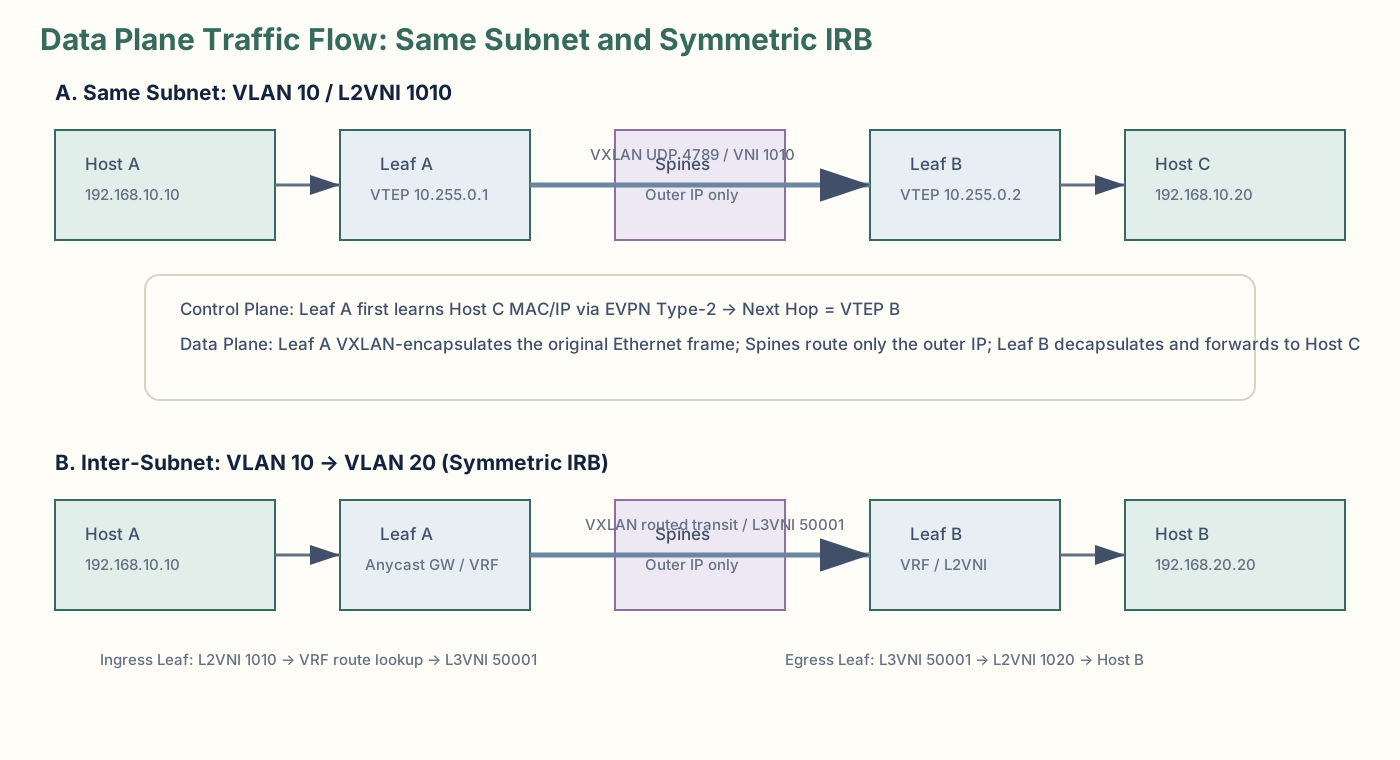
Example:
Host A: 192.168.10.10 / VLAN 10 / L2 VNI 1010 / Leaf A
Host C: 192.168.10.20 / VLAN 10 / L2 VNI 1010 / Leaf B
Control plane first
- Leaf B learns Host C locally from the access interface.
- Leaf B originates an EVPN Type-2 route for Host C's MAC/IP.
- MP-BGP EVPN advertises the route to Leaf A, directly or through route reflectors.
- Leaf A now knows that Host C is reachable via VTEP 10.255.0.2 in L2 VNI 1010.
Then the data plane
- Host A sends an Ethernet frame toward Host C.
- Leaf A looks up Host C in its L2/EVPN forwarding state.
- Leaf A VXLAN-encapsulates the inner Ethernet frame with VNI 1010.
- Outer IP destination becomes Leaf B's VTEP IP 10.255.0.2.
- Spines ECMP-route the outer IP packet.
- Leaf B decapsulates VXLAN and forwards the original Ethernet frame to Host C.
Notice the clean separation: EVPN learned the destination first; VXLAN moved the user traffic afterward.
14. Packet walk: VLAN 10 to VLAN 20 across Leafs
Use the common symmetric IRB model:
Customer-A / VRF PROD / L3 VNI 50001

Host A:
  192.168.10.10
  VLAN 10
  L2 VNI 1010
  Leaf A

Host B:
  192.168.20.20
  VLAN 20
  L2 VNI 1020
  Leaf B
Control plane
- Underlay provides reachability between VTEP loopbacks 10.255.0.1 and 10.255.0.2.
- Leaf B originates EVPN reachability for its endpoints/prefixes. Depending design, this can include Type-2 host routes and Type-5 IP prefixes.
- The route carries an RD for uniqueness and RTs that determine which EVPN instance/VRF imports it.
- Leaf A imports the relevant route into VRF PROD if its RT policy matches.
- The destination route becomes available in the VRF RIB and ultimately the forwarding plane.
Data plane
- Host A sees 192.168.20.20 is off-subnet and sends the packet to its default gateway.
- The default gateway is normally a distributed anycast gateway present consistently on Leafs that host that VLAN.
- Leaf A performs a Layer-3 lookup in VRF PROD.
- Leaf A determines the remote VTEP that can reach the destination.
- In symmetric IRB, the routed transit uses L3 VNI 50001 between VTEPs.
- Spines route the outer IP packet only.
- Leaf B decapsulates the packet, performs the egress tenant routing/adjacency operation, moves it into destination L2 VNI 1020 and sends it to Host B.
15. Spine as transit vs Spine as EVPN route reflector
Do not assume every Spine is automatically an EVPN BGP peer. There are several designs:
- Spines can be pure underlay transit only.
- Spines can also act as MP-BGP EVPN Route Reflectors (RRs).
- Dedicated route-reflector nodes can be used instead.
- Leaf-to-Leaf full-mesh EVPN peering is possible but operationally unattractive at larger scale.
If the output of show bgp l2vpn evpn summary on a Leaf shows peers 10.10.95.121 and 10.10.95.122, those are EVPN overlay peers in that command's context. They may physically be Spines and may also participate in underlay routing, but those are separate logical functions.
16. Cisco NX-OS CLI: common verification commands
Exact syntax can vary by NX-OS release and feature set, so use context-sensitive help on the target platform. The commands below are common operational patterns.
A. Underlay health
show ip interface brief
show interface status
show interface counters errors
show port-channel summary

show ip route
show ip route 10.255.0.2
show bgp ipv4 unicast summary
show bgp ipv4 unicast
ping 10.255.0.2 source 10.255.0.1
traceroute 10.255.0.2 source 10.255.0.1
B. EVPN BGP session
show bgp l2vpn evpn summary
show bgp l2vpn evpn
show bgp l2vpn evpn neighbors
show bgp l2vpn evpn neighbors 10.10.95.121
C. NVE / VXLAN state
show interface nve1
show nve peers
show nve vni
show nve vni detail
D. Layer-2 EVPN / endpoint state
show l2route evpn mac all
show l2route evpn mac-ip all
show mac address-table
show mac address-table vlan 10
show ip arp vrf PROD
show ip arp vrf PROD 192.168.10.20
E. Type-2 / Type-5 route inspection
show bgp l2vpn evpn

# On releases that support route-type filtering, use context help, e.g.
show bgp l2vpn evpn route-type ?
show bgp l2vpn evpn route-type 2
show bgp l2vpn evpn route-type 5
F. VRF / L3 VNI / route installation
show vrf
show vrf detail
show ip route vrf PROD
show ip route vrf PROD 192.168.20.0/24
show bgp vrf PROD
show bgp vrf PROD ipv4 unicast
show forwarding route vrf PROD
G. VLAN/VNI mapping
show vlan brief
show running-config vlan 10
show nve vni
show running-config interface nve1
show running-config vrf PROD
H. Useful physical / transport checks
show interface ethernet1/1
show interface ethernet1/1 counters errors
show interface ethernet1/1 transceiver details
show queuing interface ethernet1/1
show system internal interface counters errors
17. How to read show bgp l2vpn evpn summary
A useful real-world pattern is that NX-OS may first show generic BGP neighbor statistics, then a breakdown of EVPN route types received from the same neighbors.
BGP summary information for VRF default, address family L2VPN EVPN
...
Neighbor        V   AS     MsgRcvd  MsgSent  Up/Down  State/PfxRcd
10.10.95.121    4   65001  ...      ...      1y27w    5448
10.10.95.122    4   65001  ...      ...      1y27w    5448

Neighbor        Type-1   Type-2   Type-3   Type-4   Type-5
10.10.95.121       0      4394       0        0      1054
10.10.95.122       0      4394       0        0      1054
The second table is not a second set of BGP sessions. It is a per-route-type breakdown for the same two peers.
4394 Type-2
+1054 Type-5
-------------
 5448 total prefixes received
This is a quick way to explain why the same neighbor IP appears twice in the command output.
18. Troubleshooting methodology: control plane to data plane
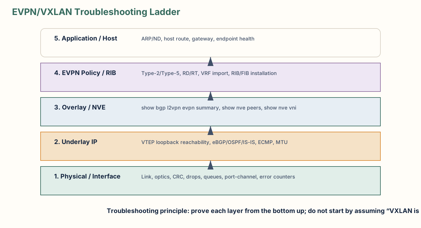
When a tenant route or host is unreachable, avoid jumping directly to “the GPU is broken,” “VXLAN is broken,” or “BGP is broken.” Work layer by layer and prove each dependency.
Stage 1 — Scope
- One host, one VLAN, one VNI, one VRF, one rack, or entire fabric?
- Only east-west, only north-south, or both?
- Layer-2 same-subnet failure or Layer-3 inter-subnet failure?
Stage 2 — Physical and underlay
show interface counters errors
show port-channel summary
show ip route <remote-VTEP>
ping <remote-VTEP> source <local-VTEP>
show bgp ipv4 unicast summary
Check CRC errors, drops, MTU consistency, optics, port-channel members and ECMP reachability.
Stage 3 — Overlay adjacency
show bgp l2vpn evpn summary
show nve peers
Verify MP-BGP EVPN session state and NVE peer state.
Stage 4 — Is the EVPN route present?
show bgp l2vpn evpn
show l2route evpn mac all
For host reachability, look for Type-2. For prefix reachability, look for Type-5 where used by the design.
Stage 5 — Is policy correct?
Inspect RD/RT and the target VRF's import policy. A route can exist in the global EVPN BGP table but fail to enter a VRF because the RT does not match.
Stage 6 — Did the route install into the VRF RIB?
show ip route vrf PROD 192.168.20.0/24
show bgp vrf PROD ipv4 unicast 192.168.20.0/24
This is a key distinction: EVPN learned it is not the same as the VRF installed and can forward it.
Stage 7 — Data plane
show nve vni
show nve peers
show interface nve1
show forwarding route vrf PROD
show interface counters errors
At this point verify the correct VNI, VTEP next hop, encapsulation path, MTU and interface/queue counters.
19. Concise interview answers
Why EVPN/VXLAN instead of traditional VLAN/STP?
“A routed spine-leaf underlay removes large Layer-2 failure domains and lets us use ECMP across all fabric links. VXLAN gives us scalable overlay segmentation, while EVPN uses MP-BGP to distribute MAC, IP and prefix reachability instead of relying on broad flood-and-learn. That makes the fabric more scalable, predictable and easier to operate.”
What is the difference between EVPN and VXLAN?
“EVPN is the control plane and VXLAN is the data plane. EVPN runs as an MP-BGP address family over TCP 179 and tells VTEPs where endpoints or prefixes live. VXLAN encapsulates actual tenant traffic over UDP 4789 between VTEPs.”
Type-2 vs Type-5?
“Type-2 advertises endpoint MAC and optionally IP reachability. Type-5 advertises IP prefixes. I think of Type-2 as endpoint-level reachability and Type-5 as routed prefix-level reachability.”
RD vs RT?
“RD makes VPN routes unique inside BGP. RT is an extended community that controls which EVPN instance or VRF imports and exports a route. RD is uniqueness; RT is policy.”
What is an L3 VNI?
“An L3 VNI represents an IP-VRF in a VXLAN fabric, particularly in symmetric IRB. L2 VNIs represent bridge domains; the L3 VNI carries routed tenant traffic between VTEPs for that VRF.”
How would you troubleshoot a missing Type-5 route?
“First I confirm EVPN BGP is up and the Type-5 exists in the EVPN table. Then I check its RT against the target VRF import RT. Finally I verify the route is installed in the VRF RIB and confirm NVE/VXLAN forwarding state.”
20. Diagram briefs for a separate diagram agent
The site package includes diagrams/README.md with six production-ready briefs. Recommended visuals:
- Traditional VLAN/STP vs EVPN/VXLAN spine-leaf.
- VLAN → L2 VNI → VRF → L3 VNI hierarchy.
- MP-BGP EVPN control plane with RD/RT, Type-2 and Type-5.
- Same-subnet VXLAN packet encapsulation.
- Inter-subnet symmetric IRB using L3 VNI.
- Troubleshooting ladder from physical → underlay → overlay → policy/RIB → data plane.
21. Final cheat sheet
| Concept | One-line definition |
|---|---|
| Spine–Leaf | Predictable Clos fabric; Leafs attach workloads, Spines provide L3 transit. |
| Underlay | Infrastructure IP network that makes VTEP loopbacks reachable. |
| Overlay | Logical tenant network built over the underlay. |
| EVPN | MP-BGP control plane for endpoint/prefix reachability and policy. |
| VXLAN | UDP-based data-plane encapsulation between VTEPs. |
| VTEP | VXLAN Tunnel Endpoint; performs encapsulation/decapsulation. |
| L2 VNI | Overlay Layer-2 bridge domain; typically maps to one VLAN/BD on participating Leafs. |
| L3 VNI | Overlay Layer-3 tenant/VRF context used in symmetric IRB. |
| VRF | Separate routing table / tenant Layer-3 isolation boundary. |
| RD | Makes VPN routes unique. |
| RT | Controls route import/export membership. |
| Type-2 | MAC/IP endpoint advertisement. |
| Type-5 | IP prefix advertisement. |
| TCP 179 | BGP/MP-BGP EVPN control-plane transport. |
| UDP 4789 | VXLAN data-plane destination port. |
Five commands to remember first
show bgp l2vpn evpn summary
show bgp l2vpn evpn
show nve peers
show nve vni
show ip route vrf <VRF-NAME>
Troubleshooting dependency chain
Physical
  ↓
Underlay IP reachability
  ↓
MP-BGP EVPN adjacency
  ↓
EVPN route present (Type-2 / Type-5)
  ↓
RD/RT & import policy correct
  ↓
VRF RIB/FIB installation
  ↓
NVE/VNI/VTEP data plane
  ↓
Host reachability